BS Vignette
Video walk-through
(May expire at some point)
http://subscriptions.viddler.com/PREPARE_INC/krk9ce
NOTE: This walk-through is very useful, however it has the exact same mistakes as the NCARB solution, so take it with a bit of a grain of salt.
Documented mistakes on the NCARB vignette solution:
1) 2x4 lights in Architect’s Office are not spaced correctly per lighting diagrams
2) lights in Drafting Studio are not centered (if they were, they would line up with the Conference Room lights)
3) lights in Reception could be more centered
4) return grilles in Drafting Studio and Conference Room are not supported on three sides by the ceiling grid (lights do not count for support)
5) return grilles and diffusers should be separated by 4' minimum (Architect's Office)
4) for efficiency’s sake, there is no need to jog the rigid duct to the west after it exits the south riser shaft wall (the only reason would be to leave room to properly show the flex duct from the Supply Closet diffuser connecting to the rigid duct)
5) it is possible to connect the rigid duct for the supply air to the long side of the Supply Riser.
Accent lighting - Note that the first diagram is a failing solution.

From Lug-Nut
Mechanical Electrical
Frequently Asked Questions:
Q. Does it matter which way the damper points?
A. This appears to be a minor issue at most. The long leg of the symbol must be parallel to the wall…either in the center of the wall or at the face of the wall.
Q. How do I center the grid precisely?
A. You don’t. Just get it as close as you can. The snap setting will not permit exact centering.
Q. What if I have ceiling tile slivers?
A. Doesn't matter. This is a ME vignette, not a pretty ceiling tile vignette. Center the lights.
Q. What is the ideal distance from the wall for lights?
A. That depends on the type of light and the lighting chart that goes with it.
Q. I can’t get the lights to fit the room to provide the ideal requirement. Should I over or under light the room?
A. Decide which based on the use of the room.
Q. What is the ideal distance between supply diffusers and return grilles?
A. A minimum of 4’ is recommended, but the farther apart the better.
Q. Should supply diffusers be placed on the window side of the room?
A. There is no evidence that this matters to NCARB.
Q. Can a flex duct supply more than one diffuser?
A. No. This is clearly defined in the program.
Q. The program specifies 1 set per 144 s.f. or portion thereof. If a room has 145 s.f., should I place one or two sets of supply/return? Do I just round up or down?
A. 2 sets should be provided as a strict interpretation of the requirement but…the 3.1 sample passing solution had a room at 145 s.f. with only one set. The program also said to be efficient. An additional set for 1 s.f. is not efficient. Catch 22. If you are over the required area, add the extra set to be safe.
Q. How many accent lights do I need?
A. That depends on the lighting chart. Determine how far from the light you can get the required lighting level. Draw sketch circles that size. Place them along the appropriate wall so that their intersections occur at the face of the wall. Then place the accent lights at the center of each circle. The goal is to cover as much of the wall as possible. Note if you change the distance between the lights, you change the distance from the wall as well because the intersection point of the sketch circles will change.
Common Mistakes:
1. Inadequate separation between supply & return.
2. Return grilles not supported on 3 sides by the grid. They’ll fall out. Do not assume the software is smart enough to place grid on the 4th side of a 2x2 light.
3. Incorrect light spacing. Read the lighting charts carefully. The current NCARB passing solution (2009) shows incorrect light spacing in the Architect’s Office.
4. Connect the flex duct to the center of diffusers, not the edge.
5. Grid overlapping ceiling elements.
6. Rigid duct crossing joists when not within 2’ of a beam or bearing wall.
7. More than one rigid duct for each riser. Adding an extra damper wastes money.
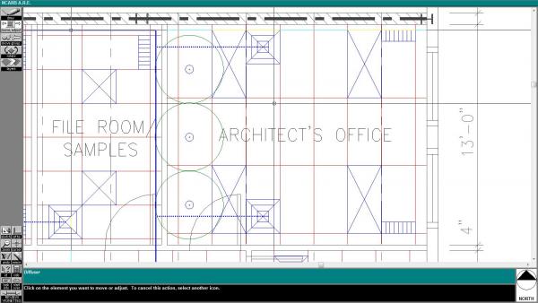
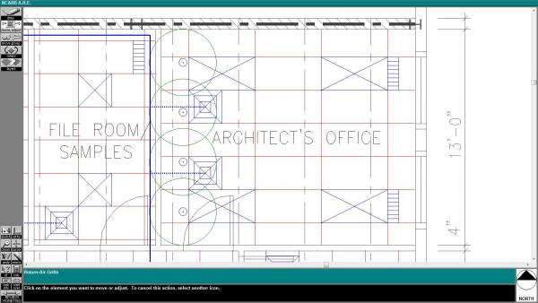
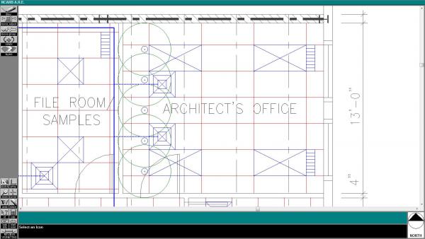
Accent Lights:
See the diagrams below. The first one does not work. The sketch circles must intersect at the wall. The number of accent lights depends on their distance from the wall.
Check List
Read program carefully. Jot down pertinent notes.
Read program carefully. Jot down pertinent notes.
- Draw grid in first room.
- Draw lighting fixture at ideal intervals. Do not worry about centering yet, just get the distances correct. For example, if your lights are to be 4’ apart just start 2’ off the wall and place the fixtures at 4’ intervals. Stop when you are 4’ or less from the wall. Lights shall be no closer than 1’ from the wall and no further than 4’ from wall. Ideally, lights should be 3’ from walls due to bounced light from fixture combining with direct light on work surface at perimeter of room to meet desired illumination levels. (Assuming a 2’ spread of light).
- Use the “move group” tool and shift the grid and lights so that they are centered on the room. If the layout does not appear acceptable, move the grid off to the side and either rotate it and try again or if another fixture is available to use try placing them in the same manner as above.
- Continue for all rooms. Verify that spaces with different fixtures have the correct fixtures, and if rooms are NOT to have the grid then a grid is not provided. A grid can still be used to layout these spaces if the module is a 2 or 4’ module but make sure you delete it afterwards. If the spacing is other than a multiple of 2’ then draw sketch circles and place them side by side filling the room. Then place the fixtures in the center of the circles.
- Click on the grid in the first room and read the square footage on the screen below. Determine the number of diffusers and returns based upon the program requirements.
- Spread diffusers out for optimum air flow. Do not place in front of door or against walls. In front of windows is a good location.
- Place returns at least 4’ away from diffusers at opposite sides of room. Do not place return against wall.
- Support registers/diffusers on 3 sides.
- Repeat for all rooms.
- Place fire dampers at supply and return risers. Short leg points in the direction of airflow.
- Draw short length of duct from center of return riser to outside edge of fire damper to plenum air space.
- Determine where rigid duct can be run perpendicular to joists and draw rigid duct out of riser and, following the program rules, over to a point between two joists that is perpendicular to the center of a line drawn between the two outermost diffusers to be connected to this run of duct. If necessary, branch a second run of rigid duct to pick up another string of diffusers in the same manner.
- Draw duct portion perpendicular to joists in allowable area maintaining half the allowable distance from the wall/beam/allowable zone. Ducts have a thickness and representative line indicates center of duct so if you draw your duct the specified distance the duct will actually be out of the allowable zone.
- Draw rigid duct between joists to a point perpendicular to the furthest diffuser for that run of duct. Do not turn rigid duct back towards risers, use additional branch of duct parallel to first branch if necessary to pick up more diffusers.
- Connect the diffuser to the rigid duct with flex duct no more than 10’, connected to the center of the diffuser. Flex duct can run perpendicular to joists and can run on top of lights.
- Does this imply that rigid duct can not run over lights?
- Repeat for all diffusers for that branch of duct.
- Repeat with second branch of duct if necessary. Try to keep all diffusers from a room on the same main branch.
- If rigid return duct is called for, provide in the manner described for the supply duct.
- Verify all rooms are properly lit, adequately ventilated, and all ductwork is continuous.
